This is part of the “APRS Tracker on STB” Project that I’ve posted earlier, this time is the effort to add PTT (Push To Talk) signal from the USB sound card, in lieu of tapping the RTS (or DTR) signal from a USB to Serial adapter. PTT is the signal to the radio to switch to Transmit mode to send the data in audio form.

As a background, this effort was triggered while reading the User Guide of Direwolf soundmodem application that mentioned of the possibility of utilizing GPIO3 from the CM108/109/119 sound chip to drive the PTT signal, and the fact that I’m running out of USB port in the STB, without resorting of an external USB-hub.
Parts required:
- CM108-based USB soundcard
- Resistor 10 kOhm
- Transistor (2N222 / 2N2222 or equivalent)
- DE9 female connector and shell
Required documentations:
- Direwolf user guide, specifically the following pages: 61-62
- CM108 datasheet
- The first documentation that shows the basic procedure,
- And especially this documentation that shows a very common USB sound card dongle in Indonesia, so I went to purchase the similar looking one:
Unfortunately, when I opened the case, this one has the chipset covered with a hard plastic blob :

So with a Dremel tool I bravely tried to scrape it off:

I made a small progress as you now can start see the reflection of the pins under the black plastic:

I gave up and went to purchase a more expensive USB sound dongle that has the chipset clearly uncovered:
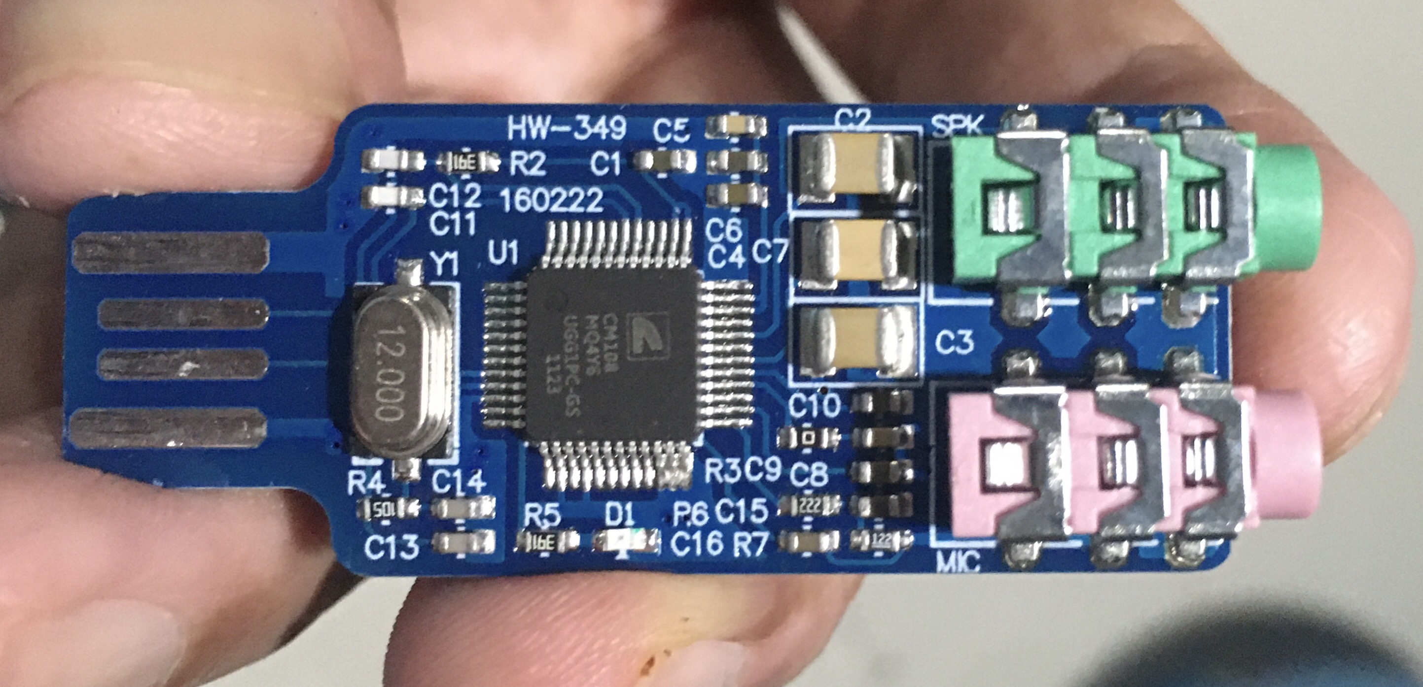
SECTION 1 – Tapping Pin 13
This is the most difficult part of this project, to solder a wire to Pin 13 of the sound chipset to tap the GPIO 3 signal.
After several failed attempt replicating the web documents that were using thin wire to solder to Pin 13, I developed a different strategy of using the solid wire of the 10K resistor to be able to finely aim to Pin 13 prior to soldering. And to ensure the whole thing is not moving, I glued the resistor to the board. Here are several pictures of the process:
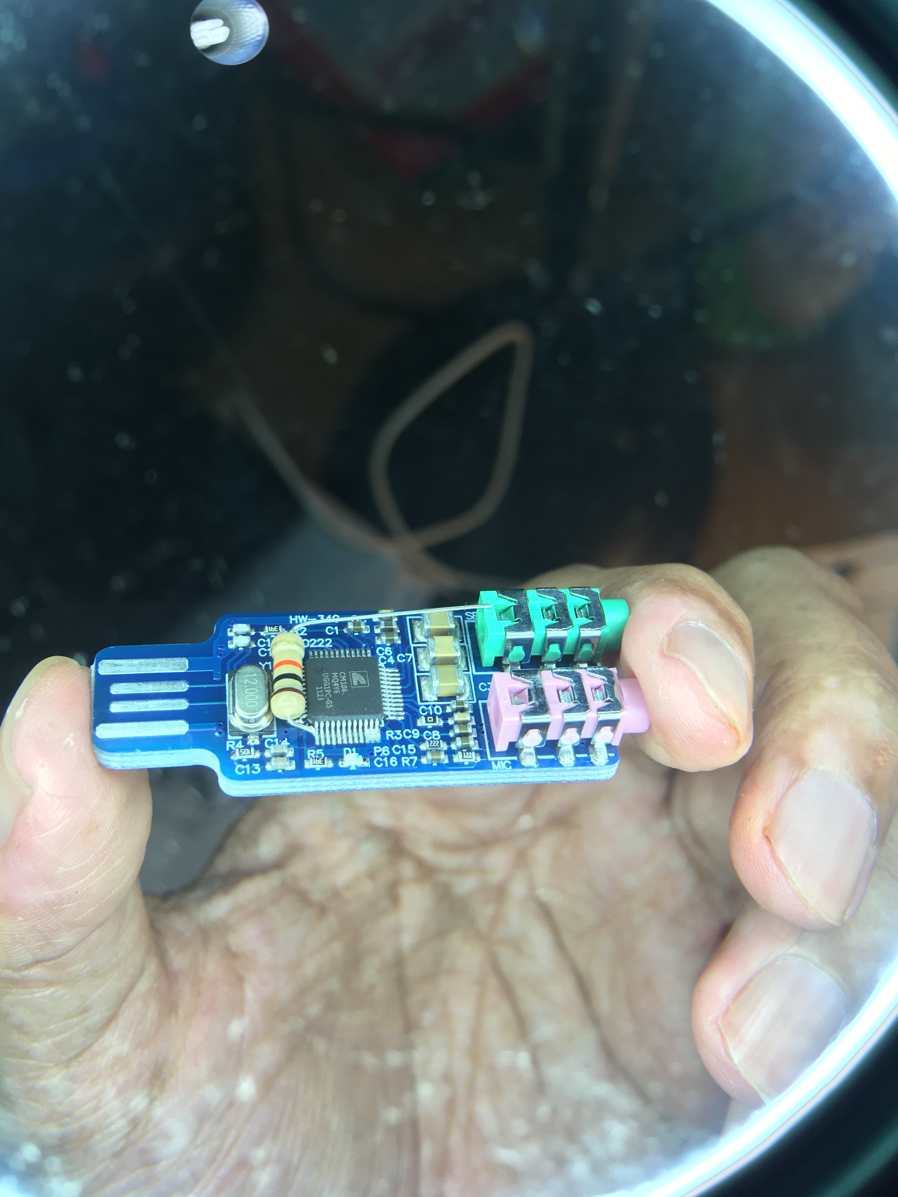


Note:
- to ensure a quick soldering process, make sure you tin the end of the resistor wire.
- If you happen to solder bridge to Pin 14, quick touch with a clean solder tip to the bridge will quickly remove the bridge
SECTION 2 – Transistor and Connector
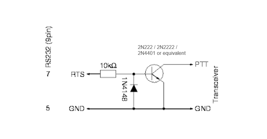
The next part is to add a transistor and wire up to a DE9 connector for connection to a radio, which in this case I use a typical 1-transistor circuit, but the RTS input is replaced with Pin 13 signal:
Here is the picture of the board with the cable and DE9 connector (wired as TNC2 / OpenTracker Radio Port) prior to installing the transistor:

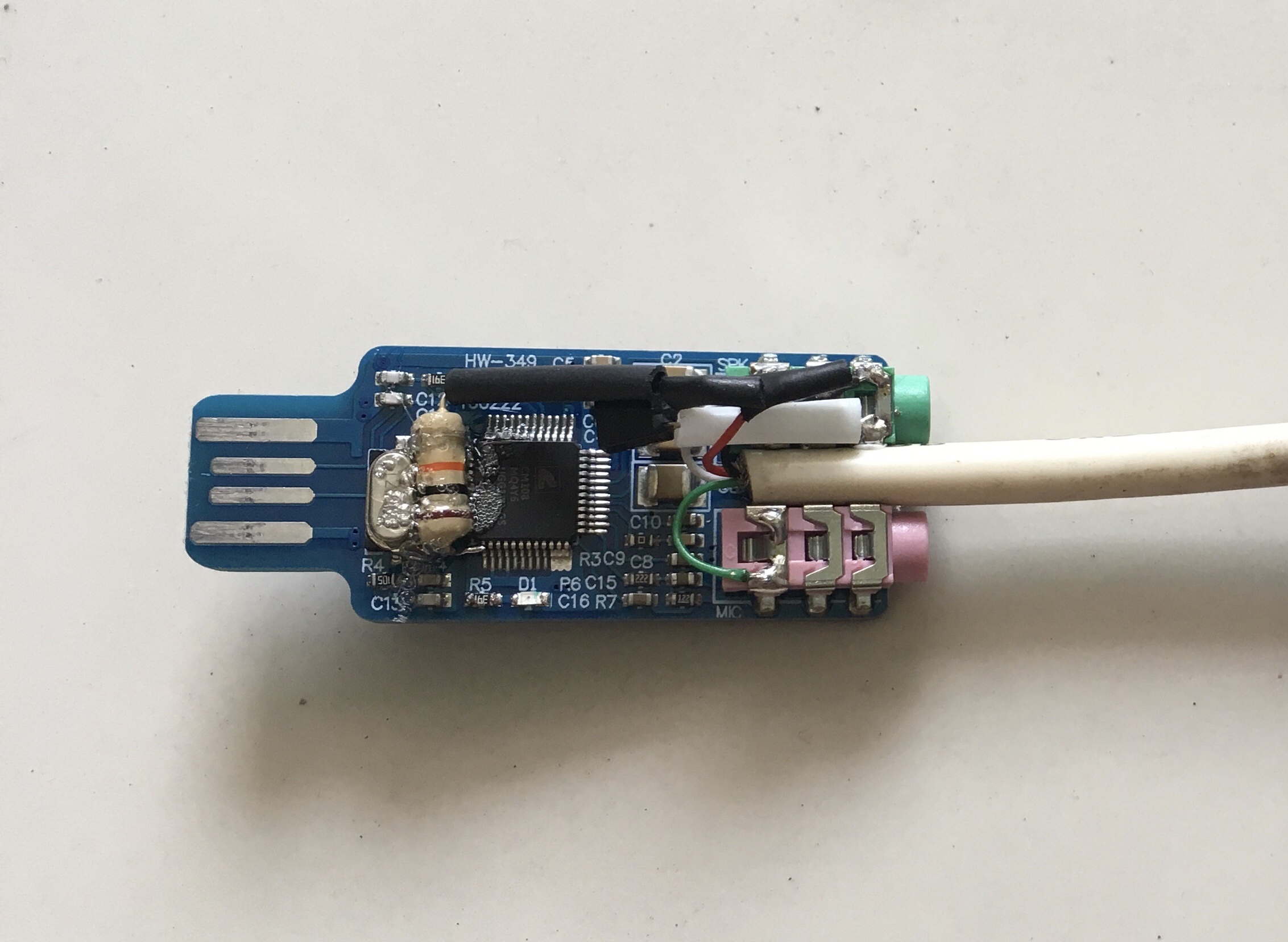
Here is the complete wiring diagram for this project:

SECTION 3 – Testing
To test this modified USB sound card I use an APRS Gateway made on a set top box (STB).
First prepare the correct radio cable, in this case for Baofeng UV82 dualband HT:

Here is the picture of the USB board tested on an APRS gateway:
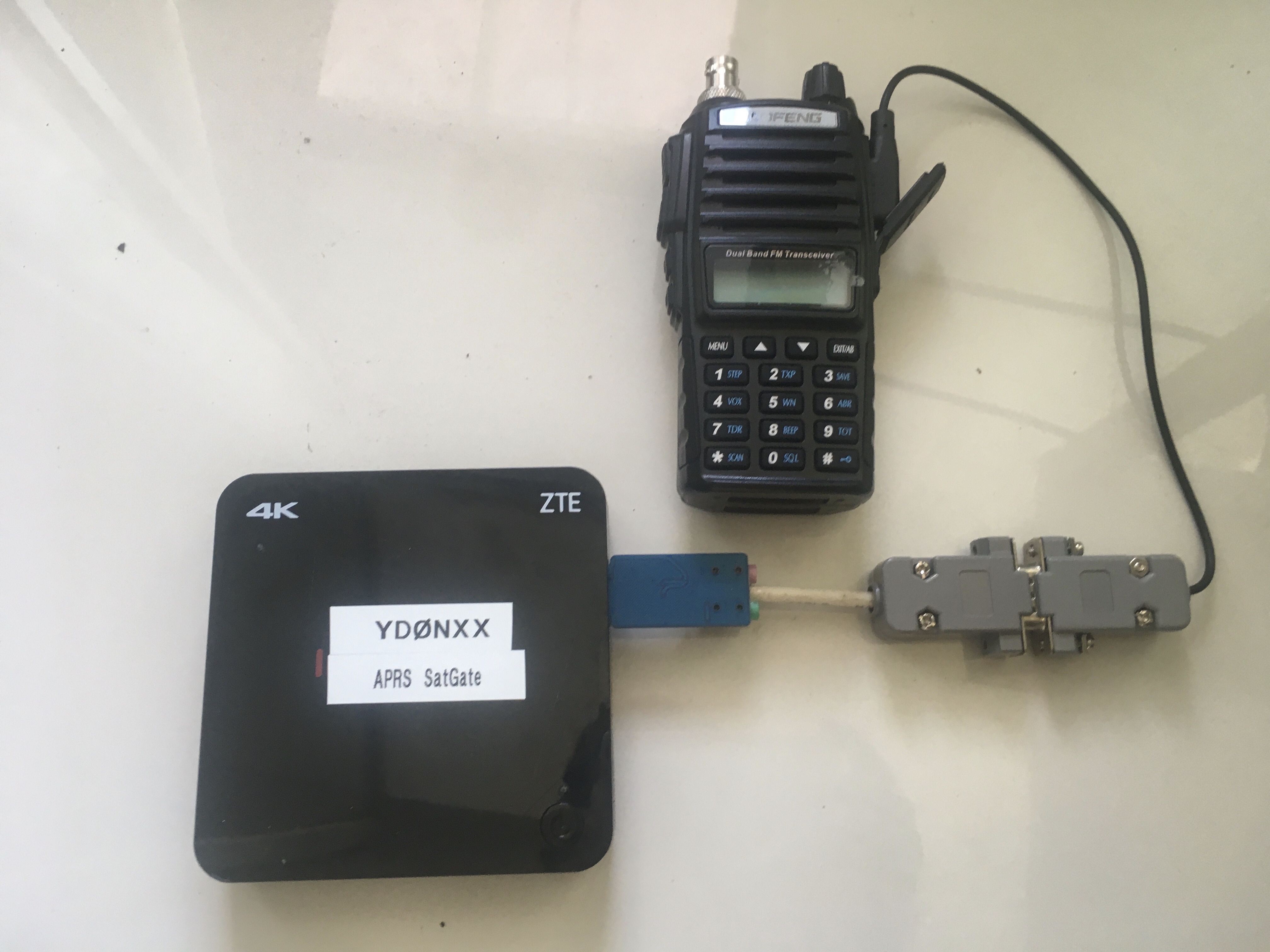
After power-up we need to check the presence of the board:
lsusb
Then modify the direwolf.conf file to enable the the new PTT onboard by adding:
PTT CM108
And change the beacon to transmit thru the radio instead to internet server:
Beacon
SECTION 4 – Wrap in Heatshrink Tube
After confirming that all functions are working fine, I wrap the board in a clear heatshrink tube to enhance the strength and prevents possibility of touching any of the components in the future.


Any text below is not mine.
February 12, 2022 at 8:21 pm |
[…] next stage for the modification of the CM-108 card now follows. Follow the link to the brilliant post by […]